4' (AKA 5 foot) Falcon build

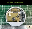
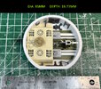
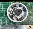
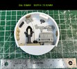
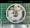
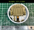
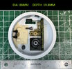
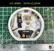
As requested, these are the dimensions I am using for my build's mandible mechanical pits.

NOTE: Everyone's build is going to be slightly different. So your mileage may vary with dimensions that work for you. As I mentioned in another post further up, I started all my pits at 91mm, then added 1mm or 0.5mm strips inside as required, dry fitting the parts until they seemed to be in the correct places relative to each other.

Height wise, that was determined by both the greeblies and where they cut off according to the filming model. As well as how two pits stack on each other, and still fit inside the mandible.

Total height of the mandibles is 2" or 50.8mm
The top and bottoms of the mandibles are 3mm each (so 6mm)

50.8 - 6mm = 44.8mm total height to fit both mechanical pits. You probably want to have a 0.5mm buffer too, so now you're at 44.3mm total for both. If you exceed that, then one (or both) of the two pits in the stack is too high.

I also used the Bandai kit as a rough guide. But we all know that is prone to error.

edit - one of those pit's isn't quite finished yet. I haven't settled on the 'gear' greeblie for one of them yet.
IMG_4621.jpgIMG_4622.jpgIMG_4623.jpgIMG_4624.jpg

IMG_4625.jpgIMG_4626.jpgIMG_4627.jpgIMG_4628.jpg
 
Last edited:
Dave,

GREAT information, and lovely overhead reference shots -- I am right-clicking and downloading them all now. The pits are, to me, one of the key proofs that in order to build a Falcon, you have to build TWO Falcons: one to screw it up, and one to get it right. I now have nearly a wall-art displayable collection of misbuilt Falcon pits.

And I'm looking at yours and realizing other key things regarding interpretation of these things, among which are as follows:
1.) I "assumed" a constant diameter, and "made it fit" whether it was 3.5"OD or not, THAT'S what it "had to be" because I liked the idea of uniformity
2.) I "cleaned up" and "made square" as many of my pits as possible, "perfecting" what I found ILM to be imperfect in their execution of, which is pure artistic liberty, as though I had the original blueprints from the Corellian Engineering Company and could execute perfectly a fictional space ship. So where the real prop has the fat/skinny pipes in the "wrong" relationship to the fat/skinny sides of the Handley-Page engine greeblies, I "fixed it" so that the pipes didn't adjoin a portion of the engine that they were "too large" for, like so:
1741789211356.jpeg

Now there were TWO ways to interpret, and thus "fix" this particular problem:
a.) Use the reverse-pipe-location as they did on the original, but make the larger pipe still small enough to fit on the skinny side of the engine greeblie
b.) Use the fixed-pipe-location to match the skinny/fat sides of the engine greeblie, but using the same size pipes as on the original.

So the "interpretation" is key here, in my opinion: my solution only changes ONE element (Location, not Size), thus maintaining "original" greeblie status as much as possible, but reverses them so they "look better" and my justification as follows: on set, NO ONE is going to see, notice, or care that "those pipes don't fit into those engine blocks" at 24 frames per second. But in a static model on display, EVERYONE is going to notice, and you get either a.) the satisfaction of saying, "Yep, that's how quick/rushed of a job they made on the original" or you get the satisfaction of saying, b.) "Yep, that's inaccurate to the original, but looks better and is how they 'should' have done it if they weren't over budget and past deadline." And you also get to say sentence b to exactly 12 other humans on planet earth, while the rest of the world seeing your model looks at it and goes, "Wow, those ILM guys were genius at making it look realistic," as opposed to thinking the opposite.

Anyway, it sure is fun to have another great set of mandible pits to compare with. If I make a third set of mandible pits, I'll likely either start with a 3.75"OD tube and then "layer in" (as you've done) extra styrene to reduce down the overall OD, or else do them purely from "wrapped" styrene (instead of Plastruct tubestock) like Eagle1 did.

The NUMBER of model kits needed to purchase JUST FOR THE LANDING GEARS for the mandible pits is insane, but happily these can still be built as regular airplane models in the "wheels up" position because most of these donors ONLY use the landing gears, and nothing else.

Anyway, thanks for your post and pictures -- very helpful, and very inspiring.
 
Last edited:
On this pit, as you can see here, I also added more depth to the back section of the tank deck so that there would be no gap between the tank deck and the curvature of the mandible pit wall:
1741790284957.jpeg


1741790318980.jpeg


Which, when trimmed and sanded down, looked like this:

1741790370409.jpeg


So that, in situ, it could look like this:
1741790463660.jpeg


So here too is an "interpretation" that I made that, in my opinion, "looks better" than the original. My build philosophy ended up being simply this: I'm not building a studio scale perfect replica of a film-used miniature; I'm building a Correllian Engineering Corp YT-1300 in 1/20.5 scale. And I'm taking Han Solo's advice and "making a lot of my own modifications along the way."
 
Thank you.

I struggle with the imperfections on this project all the time. And by imperfections, obviously I'm introducing my own, but I am really speaking of those that are on the original filming model. For example, if you look at the pit that is in the very first thumbnail (top far-left) in my post above, the back edge of the King Tiger deck is not parallel to the Armored Command Post part. When you look at it, it clearly looks cock-eyed and I'm sure some people will think it's my mistake, but when you look at the 'real thing' that's not aligned either.

I explained in my first video that the OCD in me is very conflicted. Do I fix things? Or do I make things accurate?

One of mine probably needs to be adjusted. I could probably have gone an extra mm inwards on ID for one of them. But I'll base the decision to fix it on how much sleep I lose over it.
 
Studio Scale perfection in the Falcon mandible maintenance pits is a very humbling criteria. Starting to become nervous about the disc pits when you guys post those photos down the road. Apocalypse Now- - - - “The horror, the horror”
 
For example, if you look at the pit that is in the very first thumbnail (top far-left) in my post above, the back edge of the King Tiger deck is not parallel to the Armored Command Post part. When you look at it, it clearly looks cock-eyed and I'm sure some people will think it's my mistake, but when you look at the 'real thing' that's not aligned either.
That would be their problem, not yours. I wouldn't worry about the inner minds of people who can't imagine that the little details of a filming model from the 1970s weren't applied with CAD-like precision. That goes for both deliberately added "wonkiness" and our own little "imperfections". Take pride, have fun, don't worry—and thanks for sharing your awesome work!

Fail Bob Ross GIF
 
I haven't posted much of an update on this lately, but it is still actively being built. I discovered a couple of weeks ago, that my sidewalls were too high, which was my fault for blindly following published dimensions and not checking them against sidewall castings. I'm sure if I'd created my sidewall masters before printing the frame, I'd have caught that, but...

Rather than adjusting the sidewall details, I decided to just correct the frame 3D models, and reprint a whole new frame and core. 3D printing is really quite slow, especially with large objects. So the past two weeks or so have been just printing.

The knock on benefit is that after assembling the previous frame, I found areas I wanted to improve on. So redoing the frame allowed me to do that as well.

This image shows the front and rear halves being glued to the interior ribs. Once that's all cured, I'll hit it with the palm sander to smooth out the globs of glue and level out any peaks.

1742910435509.png


For the two people waiting on my next video, I should be able to record that this week. I've had a pretty busy work schedule lately.

thanks
 
Your and SK’s stream of consciousness pit post above reminds me of my own Falcon side wall trials. Andre’s drawings served as an excellent benchmark at the beginning. Those guys used kit pats for many of their key published dimensions. Started my build before knowing about 1/72 Bandai Falcon. A mistake was buying the DeAgostini Falcon kit as a reference guide. My errors excluded, choice of materials did make a difference in “thickness” most of the time when rework became necessary.

Here are some things I think I learned regarding “section view” alignment to watch that may be of help to builders of this icon.
1. Mandible inboard side wall inside channel I.D. determined by the pontoon bridge. Obviously this sets outboard mandible inside channel I.D. If those outboard greeblies are a tight fit, you can add some disc skin before armor overlap. Very hard to fix if pontoon bridge fit is too loose. Sorry if this explanation is confusing. This skin/armor fix works on adding disc side wall height for FAGAL fit-up.
2. Disc side wall I.D. determined FALGAL castings. Note overlap of armor/skin continue to narrow that height when made to equal overall Falcon disc diameter.
3. Disc forward leading edge overlap clearance at starboard mandible surface confirmed by Duster barrels.
4. Docking ring O.D. diameter helps check the required height of the disc wall section inboard of the hatch cone.
5. Bottom main landing gear deck (plateau) top surface is confirmed by the Centurion tank hull heigh with top greeblie applied.
6. Engine grill is an insert assembly. Its inside diameter radius height should match hull chamber gap height inboard if the FALGAL side wall. About 1/2 the length of the engine deck flaps continue past the engine deck as an overlap to match the overall Falcon O.D. at that engine exhaust point.
7. You guys have said it all on pits. No need to rehash those lessons learned.

Good luck to all.
 
There you go: the second one is always better than the first iteration...as well as the third one and so forth:p:p(y)(y)(y)(y)
 
Back
Top