TheDragon
New Member
Hi,
Since the beginning of this year I had a harebrained idea to build a vacuum forming machine, which lead me down the rabbit hole of star wars helmets and now to having begun sculpting moulds to produce a stunt tk helmet. I am wanting to eventually use polypropylene to form it with the intention of making an "as close to" screen accurate helmet as I can get and make a bust to display with it (chestplate etc.).
January-ish I started planning my vacuum forming machine in solidworks and was able to build it mid February and did a lot of testing to get it working right (still have a ways to go) but as uni started up again have less time to get into the garage and tinker with it as well as run around and get supplies.
I'm not entirely new to the history behind this helmet, having mostly memorised everything that's on starwarshelmets but don't really use this forum but as I was preparing to model this helmet read a bunch of old threads and thought this forum would be a better place to go than whitearmor or a 3D modelling specific forum due to some people's knowledge of the helmet down to the bumps and brush strokes on it.
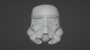
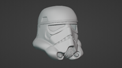
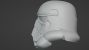
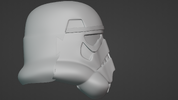
So far I have modelled the faceplate and begun on the rear of it but was eager to finish the faceplate before moving onto the rest. I'm a self taught 3D modeller and use the freeware Blender to do all my work but found it's just as powerful as any other programs out there. My plan is to get all the main features of the helmet out in my model and to sculpt all the bumps and marking inside the traps afterwards.
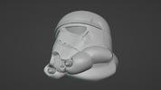
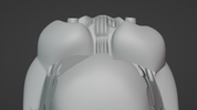
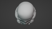
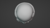
I was looking for guidance on where my model isn't correct in comparison to one of the original faceplates (as much scrutiny as possible) and where to look out for going into the next stage of adding the minor details like the bump on the dome etc. I'm mainly interested in the faceplate at the moment, and haven't finished the back as you'll tell straight away it's missing the rear traps. I am also struggling with the depth of the eyes, front traps and indents the hovi mix pieces go into as I don't have a lineage helmet to compare it too as well as the fact that the model is like 1cm in width which i'll have to scale appropriately later on.
I also have a resin printer and will eventually make the moulds with that which will hopefully capture all the details in the model.
I think that's enough yapping on my behalf though and if you have gotten this far down the page thank you and if you wanted to know anything more just ask as I'm not sure If I covered everything in this post.
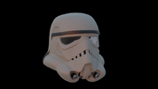
Below I have attached some images, all of them were taken with a viewport focal length of 100mm (if that helps ¯\_(ツ)_/¯ ) as well as one rendered image where I show off my bad rendering skills. If you needed any addition angles please ask as well, or to remove something like the brow or hovi mix's from around the model to see what's under it.
Thanks Again
Since the beginning of this year I had a harebrained idea to build a vacuum forming machine, which lead me down the rabbit hole of star wars helmets and now to having begun sculpting moulds to produce a stunt tk helmet. I am wanting to eventually use polypropylene to form it with the intention of making an "as close to" screen accurate helmet as I can get and make a bust to display with it (chestplate etc.).
January-ish I started planning my vacuum forming machine in solidworks and was able to build it mid February and did a lot of testing to get it working right (still have a ways to go) but as uni started up again have less time to get into the garage and tinker with it as well as run around and get supplies.
I'm not entirely new to the history behind this helmet, having mostly memorised everything that's on starwarshelmets but don't really use this forum but as I was preparing to model this helmet read a bunch of old threads and thought this forum would be a better place to go than whitearmor or a 3D modelling specific forum due to some people's knowledge of the helmet down to the bumps and brush strokes on it.
So far I have modelled the faceplate and begun on the rear of it but was eager to finish the faceplate before moving onto the rest. I'm a self taught 3D modeller and use the freeware Blender to do all my work but found it's just as powerful as any other programs out there. My plan is to get all the main features of the helmet out in my model and to sculpt all the bumps and marking inside the traps afterwards.
I was looking for guidance on where my model isn't correct in comparison to one of the original faceplates (as much scrutiny as possible) and where to look out for going into the next stage of adding the minor details like the bump on the dome etc. I'm mainly interested in the faceplate at the moment, and haven't finished the back as you'll tell straight away it's missing the rear traps. I am also struggling with the depth of the eyes, front traps and indents the hovi mix pieces go into as I don't have a lineage helmet to compare it too as well as the fact that the model is like 1cm in width which i'll have to scale appropriately later on.
I also have a resin printer and will eventually make the moulds with that which will hopefully capture all the details in the model.
I think that's enough yapping on my behalf though and if you have gotten this far down the page thank you and if you wanted to know anything more just ask as I'm not sure If I covered everything in this post.
Below I have attached some images, all of them were taken with a viewport focal length of 100mm (if that helps ¯\_(ツ)_/¯ ) as well as one rendered image where I show off my bad rendering skills. If you needed any addition angles please ask as well, or to remove something like the brow or hovi mix's from around the model to see what's under it.
Thanks Again
Attachments
-
 Front.png1.6 MB · Views: 66
 -
 UnderRight.png1.6 MB · Views: 57
 -
 Underneath 1.png1.8 MB · Views: 39
 -
 TopDown.png1.5 MB · Views: 42
 -
 Side.png1.6 MB · Views: 44
 -
 Screenshot 2024-04-01 004000.png646.3 KB · Views: 43
 -
 RightSide.png1.6 MB · Views: 43
 -
 RealTop.png1.5 MB · Views: 41
 -
 LeftSide.png1.6 MB · Views: 51
Last edited:
")