alexbailey

Well-Known Member
RPF PREMIUM MEMBER
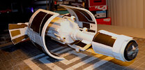
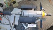
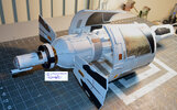
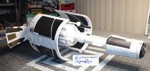
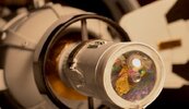
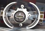
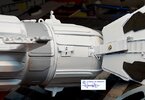
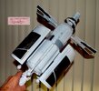
I'm working on a full scale replica of the Nomad Probe, from Star Trek. This project has been gestating for a while and I started the CAD model back in 2022.
I have been wanting to make something from Star Trek, but was having trouble finding something I was drawn to, now i've settled on this.

The dimensions were off a set of plans found on the Internet back in 2021, unfortunately I can no longer find the link.

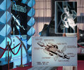
Here is a couple of screen grabs for the CAD models, these a working models and sections are not finished. I often begin making parts before having completed every detail of the model. I find at some point it's best to start making parts.
Screenshot 2024-03-20 at 19.37.15.png
Screenshot 2024-03-20 at 19.37.05.png
 
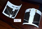
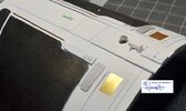
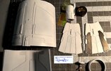
Here are the side panels with the hole for the lights. These a 1mm stainless that's been laser cut and the bent at the side.

Considered doing all of the cutouts on our CNC's but would have been very tedious and the price for the laser cutting was very reasonable.
The surface requires some brushing to finish, but I will leave that until the project is further along.

IMG_3296.jpg
IMG_3297.jpg
 
Last edited:
Here's a copy of the set off plans I used for dimensions, although I have modified much of internal structure.
I would like to provide link to the creator of the plans but unfortunately can no long find a link.
 

Attachments

  • Nomad plans 1.pdf
    3.5 MB · Views: 152
Here the base section, made of modelling board because it's easy to machine and finish.
4 section of 50mm stacked. Helpfully the using the plans I have the joins between pieces work out nicely. There are a few chips which I will need to fill in before sealing and painting.
IMG_3265.jpeg


before and after taking a skim cut to check everything looks good
IMG_3252.jpeg
IMG_3254.jpeg


Action shot, taking material of the top to end up at the correct thickness per the plans.
IMG_3256.jpeg


Finishing the more complex piece.
IMG_3261.jpeg
IMG_3264.jpeg
 
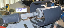
I have machined the next section up this is aluminium, this is piece that the rest of model connects too. its two layers of aluminium one 20mm round piece and then a 8mm square plate on top.

IMG_3574.jpeg
IMG_3575.jpeg


Looking here at the bottom of the plate, the countersink and counterbore holes will the underneath on the final piece. in keeping with Star Trek rule of no visible fasteners, but retaining the ability to disassemble and reassemble easily.

B4F2CF7F-6FDA-4C24-AAC9-8B8F5021E22B_1_105_c.jpeg
IMG_3585.jpeg
 
Sweet!
The other day, I collected pics of that redesign John Eaves made for that background nod in Picard, giving it a style reminiscent of the upgraded probe they designed for Voyager.. Maybe it's of some used for a before & after miniature on the plaque to go with this.
 

Attachments

  • 278150580_3112771968939823_8398701202924308496_n.jpg
    278150580_3112771968939823_8398701202924308496_n.jpg
    45.5 KB · Views: 33
  • 278141451_3112771902273163_7626161650625126081_n.jpg
    278141451_3112771902273163_7626161650625126081_n.jpg
    84.6 KB · Views: 29
  • 278116821_3112771485606538_4570503383109413569_n.jpg
    278116821_3112771485606538_4570503383109413569_n.jpg
    45.2 KB · Views: 33
  • 278143886_3112771402273213_439762580048169656_n.jpg
    278143886_3112771402273213_439762580048169656_n.jpg
    53.1 KB · Views: 30
  • 278131418_3112771182273235_1380683962934882278_n.jpg
    278131418_3112771182273235_1380683962934882278_n.jpg
    64.9 KB · Views: 31
  • 278200122_3112771305606556_8722453889012178780_n.jpg
    278200122_3112771305606556_8722453889012178780_n.jpg
    64.1 KB · Views: 32
  • 278196283_3112771105606576_370458828931947867_n.jpg
    278196283_3112771105606576_370458828931947867_n.jpg
    126.3 KB · Views: 39
  • 277586688_3109780929238927_5965112022769197266_n.jpg
    277586688_3109780929238927_5965112022769197266_n.jpg
    56 KB · Views: 36
  • 278170427_3112772038939816_2964891326505198960_n.jpg
    278170427_3112772038939816_2964891326505198960_n.jpg
    39.5 KB · Views: 28
  • 278133957_3112772135606473_4885017966139250300_n.jpg
    278133957_3112772135606473_4885017966139250300_n.jpg
    52.6 KB · Views: 26
  • Picard_and_Nomad.png
    Picard_and_Nomad.png
    400.4 KB · Views: 37
  • nomad.jpg
    nomad.jpg
    455.4 KB · Views: 38
  • 278164711_3112772538939766_3685680680140203659_n.jpg
    278164711_3112772538939766_3685680680140203659_n.jpg
    61.3 KB · Views: 34
  • 278202315_3112772418939778_6862423249283240831_n.jpg
    278202315_3112772418939778_6862423249283240831_n.jpg
    61.1 KB · Views: 37
  • 278186667_3112772328939787_3738644293778891367_n.jpg
    278186667_3112772328939787_3738644293778891367_n.jpg
    31.4 KB · Views: 30
  • 278059489_3112772255606461_4659554424045503954_n.jpg
    278059489_3112772255606461_4659554424045503954_n.jpg
    42.2 KB · Views: 27
  • 278184710_3112772195606467_4821322403182019182_n.jpg
    278184710_3112772195606467_4821322403182019182_n.jpg
    42.2 KB · Views: 24
  • 278172622_3112772475606439_7560037884383714559_n.jpg
    278172622_3112772475606439_7560037884383714559_n.jpg
    78.7 KB · Views: 37
Little more progress, I have to fit it in around the actual money making machining. finished of the brackets from the material I cut in the previous post.

70A586E8-0B2D-4060-BA54-E134FDF58414_1_105_c.jpeg
FC2AA78A-ACD2-4816-BDB1-05CC782E03BC_1_105_c.jpeg
 
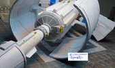
I have started work on the longer components that go on the 4 corners of the main box, the inside which is shown here is shaped the fit the panels between and tapped holes to mount the parts.

Before
IMG_5470.jpeg


After
IMG_5471.jpeg


Closer detail on the profile and holes, step shown on the right photo is to clear the bottom plate of the main box, I made a few posts ago.

IMG_5473.jpeg
IMG_5475.jpeg


The material used id significantly thicker than the final part, it ends up about half as thick as the original size, the other side has 15 - 1.5mm (Likely 1/16in originally) grooves running the length of the part, will take a while to machine.
 
Back
Top