4' (AKA 5 foot) Falcon build

They're also not straight.
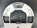
I am not sure what you mean, but note that the photograph is not from dead-on down the axis of the cockpit - the circular window frames and front face circles are not concentric with the outer circumference of the cockpit tube. I assume most of that lack of concentricity is due to the position of the camera being slightly to the left of centerline, rather than to the actual geometry of the model. The resulting image has skewed the appearance of the converging window frame longerons.
 
Look at any one of 100 different images of the cockpit cone, the lower two frames, on either side, are not straight. They have curves in them.
 
To clarify, I am not claiming the frames are straight. I just wasn't sure what conclusions were being drawn based on the comments accompanying that one photograph. :)
 
A significant milestone today. All the 3D printed parts for the primary frame structure, are complete.

View attachment 1839305View attachment 1839310View attachment 1839306View attachment 1839307View attachment 1839308View attachment 1839309

This looks really great! It seems you chose not to leave a provision for the recessed ‘well’ under the top turret like the original miniature that’s a couple inches deep.
(Ref post #154)
This design makes sense though structurally to give up that part of the original.
It’s a cool approach to construction.
 
No, there's room there for that. Those photos are of the bottom.
Ahh, ok. Was looking at your 3D model of the top and it looked like you made a ‘wedge’ and had a 2” pipe hole where the recess is. Sounds like ya got it covered though.
Keep up the good work!
 
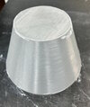
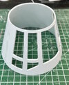
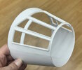
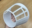
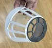
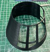
Some work done over the past couple of weeks on the cockpit cone. I tried a couple of different ways to try and create it, ultimately going back to tried and true basic model building techniques. I do not know how ILM made this part back in 1976, but I think mine wound up looking pretty close to what they created.

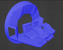
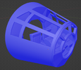
My first attempt was to 3D model the cone in Blender. I decided to go with a cleaned up symmetrical cone as my building would introduce its own imperfections.

IMG_4125.jpg


From there I just created a 3D Print of the cone hoping I could just sand it smooth. That didn't work. No amount of sanding could get it smooth enough.

IMG_4129.jpg

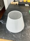
So I printed it at half thickness with the thought of putting a plastic sheet wrap around it. That didn't work out nearly as well as I'd hoped either.

My final approach was to 3D print a form that I could wrap sheet plastic around. I used the 3D model to create an interior form and then unwrapped the outer shell and printed the shape on paper so I could cut out sheet plastic from it. From that I alternated the layers so that the join seams were 90 degrees from each other. The cone itself is 2mm thick, so I made 4 layers of .5mm.

IMG_4126.jpg
IMG_4127.jpg

IMG_4128.jpg

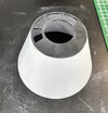
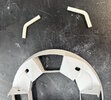
Once I had the basic plastic cone, I rough cut out the windows.
IMG_4130.jpg

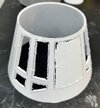
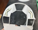
A lot of clean up and adding detail to the window edges with some T strip and I have the final product.

IMG_4131.jpgIMG_4132.jpgIMG_4133.jpgIMG_4134.jpg

I think it's pretty close. It scales up very well when you compare it to the Bandai kit, and it matches the references images I have pretty closely. And in hindsight I prefer the hand made aspect to it rather than it being 3D printed.
 
This is a great idea, Dave!
What did you use to laminate the plastic sheet together? Were there any sheet layer separation issues as you cut out the windows?
 
Just old school plastic model glue from the tube. I rarely use that stuff anymore, but for cases like this, it is the best stuff for the job. The one small area that separated during the final filling of the windows was easily fixed by just gluing the layers back together, waiting an hour, and then continuing with the work. Once all the layers were laminated together, it was really just a big 2mm thick plastic cone, any delamination was very minimal.
 
Some work done over the past couple of weeks on the cockpit cone. I tried a couple of different ways to try and create it, ultimately going back to tried and true basic model building techniques. I do not know how ILM made this part back in 1976, but I think mine wound up looking pretty close to what they created.

My first attempt was to 3D model the cone in Blender. I decided to go with a cleaned up symmetrical cone as my building would introduce its own imperfections.

View attachment 1846871

From there I just created a 3D Print of the cone hoping I could just sand it smooth. That didn't work. No amount of sanding could get it smooth enough.

View attachment 1846875

So I printed it at half thickness with the thought of putting a plastic sheet wrap around it. That didn't work out nearly as well as I'd hoped either.

My final approach was to 3D print a form that I could wrap sheet plastic around. I used the 3D model to create an interior form and then unwrapped the outer shell and printed the shape on paper so I could cut out sheet plastic from it. From that I alternated the layers so that the join seams were 90 degrees from each other. The cone itself is 2mm thick, so I made 4 layers of .5mm.

View attachment 1846872
View attachment 1846873

View attachment 1846874

Once I had the basic plastic cone, I rough cut out the windows.
View attachment 1846876

A lot of clean up and adding detail to the window edges with some T strip and I have the final product.

View attachment 1846877View attachment 1846878View attachment 1846879View attachment 1846880

I think it's pretty close. It scales up very well when you compare it to the Bandai kit, and it matches the references images I have pretty closely. And in hindsight I prefer the hand made aspect to it rather than it being 3D printed.
Love this. I see so many people who get the shape of the cone wrong, and it drives my OCD nuts. You have done it perfectly!

SB
 
The current state of the cockpit upper back wall. Not everything is trimmed and final fitted yet, but the basic shape is there.

I'm still missing two parts - the rectangular 'grill' like parts that go on either side of the instrument panel and above the Assault Gun parts. Parts maps say they're from the Roadstar but I do not think that is correct.

1723073899431.png
 
Work continues on my build's cockpit.

While I'm building the cockpit from scratch, and using the correct Morgan Roadstar parts, I find it very helpful to model everything in Blender first before cutting plastic. This allows me to validate dimensions, and where I should cut things, before I hack into plastic parts from a $200 kit. It also allows me to export the shapes as flat patterns from which I can cut out 1mm styrene.

The first thing I had to do was take the Morgan Roadstar seats and floor panel then model them in Blender. The 3D model parts don't have the Kydex texture of the real kit parts, but dimensionally they're exact and that's all I need for building up the rest of the cockpit.

The most difficult part is the lack of really clear photos of the cockpit from enough angles, which results in a lot of guesswork that I wish I didn't have to make. There are also two rectangular kit parts on the back panels that have not been ID'd yet so I'm rummaging through my kits to see if I can find them.

While not shown in the photos, I'll be using the correct 5mm LED's to light consoles and panels.

1723652306997.png

1723652533942.png

IMG_4140.jpg

IMG_4141.jpg

IMG_4143.jpg
 
Hi there.

I'm working on the centre console section of the cockpit and I'm wondering if someone has a better reference photo than I have.

This is the clearest reference for the console light panels that I have, but I can not make out the pattern on the panel just behind the throttle quadrant (?), which I've highlighted in red. If anyone has a better angle of this area of the cockpit that they'd be willing to share, I'd appreciate it.

thanks
David

1724002824218.png
 
Are these the ones you mean? I suppose it's possible, if they were cut down to 2 rows from 3. But also I think in the original part, the interior slats are closer together.
IMG_4156.jpg
 
Back
Top