You are using an out of date browser. It may not display this or other websites correctly.
You should upgrade or use an alternative browser.
You should upgrade or use an alternative browser.
First Project: The AE-35 Unit! Advice appreciated
- Thread starter Abitofcredit
- Start date
macropod80
Active Member
Perhaps, but here's my reality: the B&W image is certainly very shaky, but a couple of details I don't think are just artefacts:Hm. I think they're the same cover, rotated 180° for sure. The print looks mostly the same for me, though there are numerous artefacts in the B&W image from sharpening.
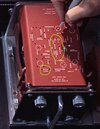
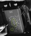 At bottom left (note I've rotated the B&W one for easier comparison) there's a clear line between two holes, with text below it, versus two lines of fuzzy text (OK, I expect you to be doubtful..). More distinct is that group in the middle: in the B&W image there's a single long line on the left, versus two short lines with a hole between them. And the text to the left of that is aligned slightly differently.
Also, I don't think the plate can be simply rotated and attached upside-down because it's shaped differently at each end. Most shots show what might be just a shadow, but I think there's actually a cutout at the front corners (to clear the projecting big screw/nut):

We're having a lot of fun with someone else's thread, aren't we. Whatever happened to the guy who started this - hope he hasn't given up?
macropod80
Active Member
I'm going to start calling this B&W unit the #2 unit, versus the hero unit seen in colour stills from the film.Mmmh, I think you're on to something mate. What really makes it different, appart from the graphics, to me is that lack of innards in that B&W unit
Originally I just noted that the little vertical circuit-board was missing - I hadn't thought, as you suggest, that the whole insides might be missing. Certainly the other enclosed units (in the storage locker and carried outside) must be much lighter, especially the way they're waved around in 'zero-G'. But I'd assumed they would just be made as empty boxes. Constructing them around emptied gyro frames might perhaps have been easier for the props guys. In which case there must have been quite a few gyros kicking around at the time, probably all subtly different in details. Another tiny detail I think I've picked on the #2:
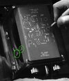 These plain triangular shapes took like these:
 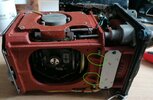 but not like the round, flat-topped bosses on the hero:
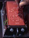
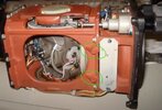 So a different frame, whatever's inside it or not.
The shots showing the #2 unit might be from early tests or rehearsals, either while the AE-35 final design was still being resolved, or perhaps as a stand-in for the good one. We know there was a lot of flux in most designs and this little prop was quite important in the plot. That shot from Trumbull's video shows an unaltered gyro, while as you noted the one in the background here:
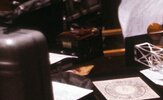 although otherwise unchanged, has had the plate on the side removed, exposing where the extra little circuit-board will appear. So it was a slow process, like most of the film.
And that shot reminds me, the two connectors on the rear end are different sizes but both the same on the final AE-35. So anyone thinking of buying a gyro needs to find an extra big Plessey connector.
joberg
Legendary Member
Yep, good research macropod80...Could be that some of "boxed" units had to be opened for a scene, as you have posted a pic of Bowman screwing (or unscrewing) the lid back on; action not seen in the final movie. Could be the "defective" unit (B&W) being tested and the other replacement (color) being tested also to make sure everything is A+...who knows how all of those were either filmed, or simply photographed and not filmed...is it part of those 17 minutes of film Kubrick cut from his original version?
macropod80 : so you are going to go for the two separate pieces, as the seller suggests?
macropod80
Active Member
No, as I said back in post#94, that was straining the bank balance just that bit too far. (And I suspect pulling the front off will be a lot easier than trying to put one back on, with all that fiddly stuff to juggle) Which is why I've been squinting at images so intently, trying to persuade myself that maybe those flats on the front struts are optional. Will be making one with round struts.macropod80 : so you are going to go for the two separate pieces, as the seller suggests?
Actually, I can see it's going to be quite involved.
macropod80
Active Member
Next problem is the knobs, clearly not the black plastic (Bakelite?) ones that come with the gyro. To me they look like this:
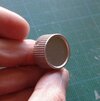 (Drew one in CAD, printed it and slapped some silver Humbrol on it.) They look familiar, like audio/electrical things that were around in the 70s (well, obviously from around 1967..). Made from a milky/translucent plastic, chrome-plated. Possibly car radios?
This kind of thing: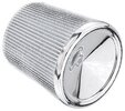
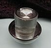 (Or have I just reached that age where everything looks familiar?) Maybe 7/8 inch dia. x 1/2 inch tall?
Any suggestions anyone?
 (Drew one in CAD, printed it and slapped some silver Humbrol on it.) They look familiar, like audio/electrical things that were around in the 70s (well, obviously from around 1967..). Made from a milky/translucent plastic, chrome-plated. Possibly car radios?
This kind of thing:

 (Or have I just reached that age where everything looks familiar?) Maybe 7/8 inch dia. x 1/2 inch tall?
Any suggestions anyone?
Last edited:
macropod80
Active Member
Well it's arrived and looks just like the real thing.
Still under lockdown so had to raid the back shed for whatever I could find to start a mockup for planning the final arrangement:

Hoarding old screws in jars really does pay off eventually, and a 3D printer helps too. Looks like it will take a bit of trial and error to nail down the exact dimensions and construction. Already looking like a few parts on the gyro need rearranging to work.
Suppose it's time to stop piggy-backing on Abitofcredit's thread and start my own build thread.
Many thanks (all the credit) to Abitofcredit for finally identifying this gyro and letting the world know about it.
Still under lockdown so had to raid the back shed for whatever I could find to start a mockup for planning the final arrangement:
Hoarding old screws in jars really does pay off eventually, and a 3D printer helps too. Looks like it will take a bit of trial and error to nail down the exact dimensions and construction. Already looking like a few parts on the gyro need rearranging to work.
Suppose it's time to stop piggy-backing on Abitofcredit's thread and start my own build thread.
Many thanks (all the credit) to Abitofcredit for finally identifying this gyro and letting the world know about it.
macropod80
Active Member
Yep the handle and knobs are printed because I couldn't go out to buy anything. Tried a while ago to find handles in hardwares, but they only had metric ones. Needs another couple of mm for 4inch. Also most modern ones don't have such a nice smooth curve on the bend - tend to have an ugly kink. Will be posting dimensions and stl files as I progress.Looking very good macropod80! Did you printed the handle?
So - next question.  What size were the sockets? We know that they machined tapered aluminium rings to fit around actual plugs. My initial thought was the large one, but looking at this I'm wondering if they didn't use the small one.
Top: actual gyroscope. Bottom: behind the scenes snapshot from 2001.

Top: actual gyroscope. Bottom: behind the scenes snapshot from 2001.
Okay, I spent a stupid amount of time last night wading through online potentiometer knob catalogues. Who knew that multiple companies specialize in such a thing? Anyway. Couldn't find anything that looks like our aluminium AE-35 friends.
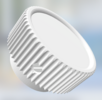
So I also threw one together in software, and I'm going to look into having machined metal ones made. My rendition looks like this. Did you go for 60 ribs in the fluting, macropod80 ? And any thoughts on the top surface - the disc. Does that perhaps have a faced surface or concentric fine circles, so you end up with that X-shaped pattern of specular highlights? Or was it just flat aluminium?
So I also threw one together in software, and I'm going to look into having machined metal ones made. My rendition looks like this. Did you go for 60 ribs in the fluting, macropod80 ? And any thoughts on the top surface - the disc. Does that perhaps have a faced surface or concentric fine circles, so you end up with that X-shaped pattern of specular highlights? Or was it just flat aluminium?
Attachments
macropod80
Active Member
I just copied the original 48 on the Sperry, but they're only mock-ups till I settle on the final design. Something finer, like 60, may look better.Okay, I spent a stupid amount of time last night wading through online potentiometer knob catalogues. Who knew that multiple companies specialize in such a thing? Anyway. Couldn't find anything that looks like our aluminium AE-35 friends.
So I also threw one together in software, and I'm going to look into having machined metal ones made. My rendition looks like this. Did you go for 60 ribs in the fluting, macropod80 ? And any thoughts on the top surface - the disc. Does that perhaps have a faced surface or concentric fine circles, so you end up with that X-shaped pattern of specular highlights? Or was it just flat aluminium?
I'm not surprised you haven't found anything modern - I think we need to be looking for vintage, maybe military/aviation gear like this kind of stuff:
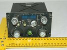
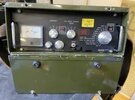
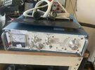 (And look at those handles!) People do actually list vintage knobs on evilbay.
If you're getting quotes you may find simple V-grooves are cheaper:
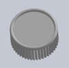 and possibly more accurate? And for the top surface, just ask for whichever is cheaper (until we find a clearer photo of the originals).
And are you sure the knobs are mushroom-shaped with that fat stalk, or is the stalk part of the body/face, like on the Sperry gyro:

