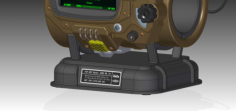
Functional Pip-boy 3000 Mk IV from Fallout 4

I have two questions concerning the design of the pip boy. First, is it within reason to be able to print the main chassis in something more durable then plastic, such as steel (Which would be really heavy) or other materials like aluminum or such. Are there any assemblies that would make this particularly difficult (IE plastic welds, unusual mounting points, etc?)

My second question is more in regard to the cassettes, after all there are 4 pins, so in theory you could make a non standard usb connection through those four pins. In essence, you could make the cartridges usb devices or thumb drives thus fulfilling their function as a data storage device and also able to fulfill the function of an object that triggers a particular response, buy simply going with a remarkably small usb storage card (Like less then 512mb that many security professionals use as a encryption key for laptops) the only major downside is the added complexity to an already complex project.
 
Raveyote

You could print it in a metal material, however metal 3D printing would require lots of alternation and post-printing re-work. Metal 3D printing is done in one of two ways: Printed in a plastic/resin, then molded and cast. Or printed using a metal powder and binding agent, then put into a oven and baked. Both methods have shrinkage involved and are not very precise. The cost of 3D printed metal is also at 10x the cost of plastic. And the 3D printers for this materials can't print something as large as the Pip-Boy.

Many of the parts in the design could easily be cast after a 3D printed master was made, however these parts are also the cheapest to 3D print. They don't add much to the overall cost. The primary component is the front face, it has all the internal mounting holes and other features which can only be reliably created with a SLS 3D printer. There are mounting holes at 90 degree angles to the face, under-cuts and other features which make even flexible casting difficult. The primary issues is casting these parts can have issues with shrinkage, which makes the items like gears looser. The CAD model would have to be altered to adjust for the casting.

The Nylon material I am using is a material I have worked with quite a bit in the past. It is very strong, even at 2mm thick. It is solid, so you can sand or drill the surface without worrying about hitting a internal void. You can dye, or prime and paint the surface. You can polish it to a smooth mirror finish. The Nylon is also self-lubricating, which makes all the moving parts work together better. The parts come out very precise, and don't need any secondary machining to work as a gear or moving part. The most I have had to do is re-drill out a hole to make a pin fit in easier. I have even 3D printed built-in threads as small as M6 into a part and had a metal nut successfully thread onto it.

----------------

In regards to the cassette idea, I gotta say that is a great idea! But I have to think of the advantages/disadvantages.
I could easily find a small MicroSD card to USB adapter that could be wired up inside the holotape. The MicroSD card could protude a tiny bit out the back of the cassette so you can pull it out and update it. The MicroSD card could then actually hold the audio/video file that is to be played back. Or a text file could be read and trigger an action on the Beaglebone. It makes the holotapes less fake, but it may also be overkill, since you won't be finding any of these in the real world, or swapping them with a fellow Pip-Boy owner.

Here are the complications:
There is only one USB jack on the Beaglebone. I plan on using that for WIFI, just because the modules are inexpensive and android ready. Adding a non-USB WIFI module is possible, but far more complicated. Even with the single USB port, I don't have physical room for even the tiny USB WIFI modules, so the USB jack will have to be de-soldered, and a header put in its place just to wire in the WIFI.

Adding a 2nd USB port requires a USB hub. Yes, hubs are cheap. However even an off-the-shelf hub simply won't fit, no matter how small. A USB hub integrated circuit that I put onto the motherboard is possible, but also adds cost and is power hungry. Remember when running on a battery I only have 3.7V (at full charge) available. USB typically requires 5V. I have seen some people who have gotten USB devices to run off 3.3V, but it really depends on the connected device.

In the end I have to balance out what features make the Pip-Boy functional as a game interface, versus what functions would make it more like a real-life Pip-Boy. Originally I had aspirations to add all sorts of sensors to the Pip-Boy.

Here is the original list of ideas which me and my friend came up with, and why they were rejected.
Sensors:
-Skin temperature
How: IR sensor pointed towards arm.
Reason rejected:: IR sensors cost $15, or require a tiny expensive to solder BGA chip. Padding may block signal.

-Relative humidity (Weather sensor)
How: Sensor IC. (~$3)
Reason rejected: Board space, and requires a custom made app.

-Barometric pressure (Weather sensor)
How: Sensor IC (~$7)
Reason rejected: Board space, and requires a custom made app.

-Accelerometer (Detect a hit to the player.)
How: Sensor ID (~$3)
Reason rejected: Board space, and requires a custom made app.

-Magnetometer (Digital compass)
How: Sensor ID (~$3)
Reason rejected: I may add this in if the Android native GPS apps can read the data, otherwise same issues as above.

-Heartrate monitor (Player health)
How: Green LED and light sensor wrapped around player's wrist.
Reason rejected: This method is how the low-cost finger heartrate sensors work at a hospital. But for it to work on your wrist you need custom processing. Watch companies barely got this work this year using a custom made sensor and processor. It is out of my reach for this project.

-Full-size Geiger counter
How: Copy the spark-fun geiger counter circuit. ($110)
Reason rejected: 500V a few millimeters from your arm. Expensive. Takes up a huge amount of board space. Pin-Diode detector is low-cost and is still a real Gamma ray detector. Even with the Pin-Diode detector, you need to put a radioactive sample within an inch to even detect Gamma rays, so it's really on staying in the Pip-Boy for bragging rights.

-Air quality sensor:
How: Multiple sensor chips ($15)
Reason rejected: Expensive, requires custom app.

At $1000 (current estimate), the Pip-Boy is already very expensive to build. There are three primary uses for this replica prop:
1) Bragging rights. And being able to say "Yes, it really works. Yes, it can detect Gamma radiation, Yes, every knob works."
2) In-Game. Increasing the immersive effect of the game. Being able to use the companion app and Pip-Boy to cause an effect in-game. Even this may require a custom app to alter the behavior of the companion app. (For example if the companion app doesn't have any keyboard input)
3) During cos-play. Being able to pull up your Pip-Boy and pull up a map or your surroundings and navigate like you do in game. Putting in a holotape and hearing an audio log play. Both of these also require custom apps.

Adding even more to the design would be cool for #1, but I think its already complex enough to impress any Fallout fan or geek.
 
Last edited by a moderator:
Thanks for answering my questions, I'm curious to see the finished product. Also out of curiosity what are the most expensive elements to fabricate?
 
21323136391_55d52166b3.jpg

Raveyote

Most certainly the most expensive single component is the front of the enclosure, simply due to its size. Shapeways quotes their pricing based on both the cubic centimeter of material used, as well as the cubic centimeter of machine space your model takes up. I pre-nested all the parts and quoted them all at once. As shown in the image above. This makes the parts quote come out to $416, which is 42% of the current estimated total cost. Once I get closer to actually ordering the 3D printed parts I will try different configurations to quote. It may be cheaper if they are all laid out flat, or ordered in smaller groups. It takes quite a bit of time to work out all the various possibilities. From what I read on Shapeways, they prefer parts to be grouped together for one project when possible. So far they have also been the lowest price for SLS by far. Their prices have also dropped quite a bit over the past year. Three years ago I ordered a 3D printed wedding topper I designed for my Niece, it cost $150, today that same part shows up on their website for $31. A 3D printed Nexus 5 mount I designed cost $230 in January, today is is listed at $170.

The circuit designs are still in progress. The major components are the BeagleBone ($55), LCD ($48), Gauge Motor ($27). But the actual circuit boards themselves (no components) will add up to over $100, even if made cheap overseas. The PCBs will require some assembly of the surface mount components, this costs quite a bit for small runs. Then there is all the various connectors, wires, and other components. These all are cheap on their own, but add up quickly. So it is actually hard to pin down the most expensive part until everything is tallied up.

----------

Small project update:

Adafruit had a great offer to get Eagle PCB Make Personal edition, and a BeagleBone for $180. The retail price for Eagle Maker is $170, so that was like getting a BeagleBone for $10. Not a bad deal. I know earlier I said I was going to use KiCAD, but I would rather have used Eagle as most of the libraries I am referencing are native to Eagle. So I have a Bealgebone, and IR sensor on the way. This will get me started.

One item which has been very difficult to get an optimal solution is all the various LED backlights I have in the circuit. The LCD screen uses a string of LEDs, there will be three LEDs for the Rad guage, and three for the Radio dial. So far I haven't been able to find any three channel LED controller which has separate brightness control over each channel. I may end up with three separate circuits.

I do think I found a good solution for the lamp on the back of the Pip-Boy. Adafuit sells these things they call Neopixels. They are LEDs with build in controllers. I thought they only came in Red/Green/Blue. But they do sell a warm-white version. They are very bright, they are a bit expensive at $0.50 each, but they don't require any additional circuitry to work. I have ordered a few to try out. If they work out well I may be able to use them on the gauges as well.
 

Attachments

  • 21323136391_55d52166b3.jpg
    21323136391_55d52166b3.jpg
    24.8 KB · Views: 168
  • 21323136391_55d52166b3.jpg
    21323136391_55d52166b3.jpg
    24.8 KB · Views: 176
  • 21323136391_55d52166b3.jpg
    21323136391_55d52166b3.jpg
    24.8 KB · Views: 166
  • 21323136391_55d52166b3.jpg
    21323136391_55d52166b3.jpg
    24.8 KB · Views: 171
  • 21323136391_55d52166b3.jpg
    21323136391_55d52166b3.jpg
    24.8 KB · Views: 173
Last edited by a moderator:


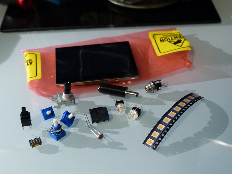
The first step in going from virtual to real: The first batch of prototype parts have arrived! I also just realized this project is a reversal of my previous gaming projects. My last few major projects were taking real-world locations and making them into virtual game maps.

I would like to thank the generous person who donated to the project, as it helped get things rolling.

The LCD is the major item. Once the BeagleBone Black arrives I will be working hard to get the screen up and running. All of the components are tiny, I guess I should have put in a quarter for comparison.

The black item at the left is the selection button. It has a large throw and very satisfying snap at the end. The item below it is the Holotape spring connector. Next are the blue potentiometers which will read the signals from the various knobs. The green item above them is the rotary encoder which will read the scroll wheel.
The orangeish round item is CdS photo sensor. Next to that is the speaker, and then the push-buttons for the Power and Light switches. Finally the power connector, and white lamp LEDs.

------------------------


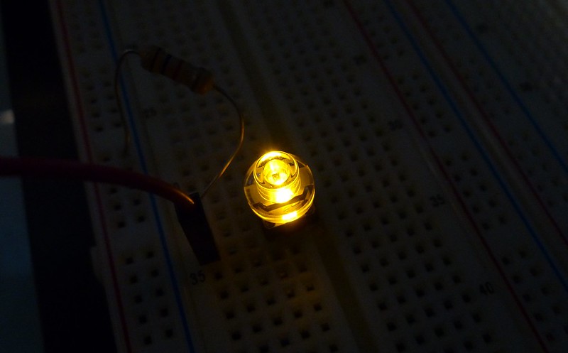
I couldn't wait to fire up the amber push button switch. The color is bright and diffidently will fit with the retro electrical look of the Pip-Boy. This weekend I will test the bright warm white LED's, and see how well their light diffuses through a few millimeters of nylon.
 
This is absolutely amazing and the speed of the progress just blows me away. I'm glad to see you are getting much support!!! Donation of mine coming soon :)


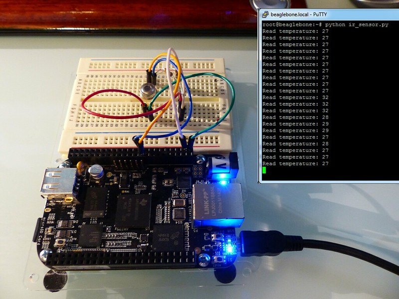
The Beaglebone Black has arrived. It took a bit of time to get everything up and running. I am not much of a programmer, I constantly have to look up examples and syntax. But I managed to read the data from the non-contact infrared sensor and feed it out to the console. Apparently my office is pretty warm at 27c (80f), but hey it's Texas and I have a 300W room heater running in here. (900W if I am gaming). The 32 degree readings are from me passing my hand over the sensor. The sensor has a wide field of view and averages out the values it reads. I can put a tube over the sensor to narrow the field of view.

The python script is amazingly small. The Adafruit I2C library and Beaglebone are doing most of the heavy lifting.

import time
from Adafruit_I2C import Adafruit_I2C
i2c = Adafruit_I2C(0x5a, 1)

x = 1
while True:
low, high, pec = i2c.readList(0x07, 3)
temp = int((((high << 8 ) | low)*0.02)-273.75) # temp in Celius
print "Read temperature: %i" % temp
time.sleep(1)

I need to order more parts before I can get the LCD screen up and running. Since most of the components I am using are surface mount, during the prototype process I will be using pre-made breakout boards when possible.


A quick project update:

One item that I wanted from the beginning of the project is a high-res LCD screen. I did extensive searches for retail available LCD screens and only could fine 320x240 screens. As mentioned earlier in the project log, I didn't want to use a un-supported off-brand LCD screens, or one ripped out of a phone.

Yesterday, I finally found a 640x480 3.5" LCD screen which is supported by a U.S. company. CrystalFontz may be a name familiar to some old-school PC modder's. They made some of the first USB character LCD screens used in PCs which had fan controllers and stats visible. In either case, they sell a 3.5" TFT LCD screen. They also have a good set of reference schematics. The new LCD screen is also a sun-light readable display, which means the Pip-Boy will be visible even outside.

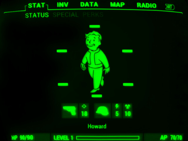
The screen costs quite a bit at $119 for one, but twice the resolution will be worth it. The old screen was 320x240, which while readable, isn't fun to work with. There is also a risk that the companion app won't even support that resolution. 640x480 is a common enough resolution that it should work. The image above is a 640x480 pixel screen shot of the Pip-Boy Mk4 interface. Shrink that image down to a small 3.5" LCD screen and it is should be very sharp.

The only catch is that the screen is only available with a restive touch-screen, which means a matte finish instead of glass, but hey the screen on the Pip-boy shouldn't be too shiny anyways.

I am now working the new display into the design, and will be ordering one to test out soon.
 
I think the downgrade to a resistive touch-screen and loss of the glass face is more of a drawback than the 320x240 LCD screen, personally.
 
I want to keep the glass also. They (Crystalfontz) is looking into a capacative touch overlay that another customer uses, it could then be added to their non-touch version. Most touchscreens are just adhered on top of a normal LCD display anyways. This type of support is one reason I select U.S. companies, even if they are selling a screen from an overseas company. They have already done all the vetting and testing.
 
If you look at the daylight comparison on the Crystalfontz product page the improvement is marginal and still wouldn't be very usable in direct sunlight.

I want to keep the glass also. They (Crystalfontz) is looking into a capacative touch overlay that another customer uses, it could then be added to their non-touch version.

That sounds promising. I just think it would be a shame to comprimise on the glass display when every other aspect of this project is being realized in such extraordinary detail.
 
Small update:

I got Android working on the BeagleBone. So far I have GPIO input/output tested and working. Nothing too special. The day job is busy this month so progress will be slow for a while. I am not sure if I will even do a build before I know the companion app can run on the BeagleBone.


Working on nothing but software gets tedious. I am having to teach myself Android programming, as well as brush up on my Linux skills which I haven't used in years.

So today I took a break and designed a stand for the Pip-Boy. It is modeled after the stand that comes with the Pip-Boy edition. The stand will have four press-in rubber feet. (No adhesive crap). The arms which hold the Pip-Boy are custom fit to the 3D model, so it will slot into the same spot each time.

To create the label artwork as a true vector drawing; I first took a close-up image of the Pip-Boy edition, and cropped and perspective corrected the label portion of the image.
I then brought that into CorelDraw for reference. I first found some high-res RobCo and Vault-Tec logos and converted those to vector art. The font I used is Monofonto which many have said is the Font used on the Pip-Boy GUI. It pretty closely matches the font they used on the label. I tweaked a few characters and spacing to make the final artwork.

These types of industrial aluminum labels are something I am familiar with. However they often cost quite a bit to make in small quantities. They are made by exposing a photosensitive black material to UV light, then washing off the material, leaving the aluminum behind to create the silver text. I even know the company here in Austin who has been making these labels so long, that they have aluminum labels on the Apollo moon landers! However, these labels are made by exposing a large sheet with multiple labels and then cutting them apart. I think I can approximate the look of this label by painting a sheet of aluminum, and then laser-etching the lettering.
 
Well I ran into a road block on the project. But this is why I design and prototype before stating a full build.

I mentioned that I got Android working on the BeagleBone, and it indeed does run. However it is pretty darn slow when it comes to android applications. The BeagleBone runs Linux pretty well, and can even run games like Angry birds on Linux pretty fast. However, apparently very little of the hardware acceleration is enabled in any of the Android builds.

At this point I have three options:

1) Skip the in-game companion app aspect of the project, and just make a Linux based, functional real-world Pip-Boy. (Geiger, temperature, Radio, GPS, etc...)

2) Keep the Beaglebone and hope that the companion app won't require much horse power. (Unlikely as it will probably use lots of 2D and 3D rendering for the GUI)

3) Find an alternative/faster Android compatible single board computer.

Currently, I am pursuing option 3. As jellis359 mentioned earlier, the Udoo Neo is an option. I had rejected it since it is an un-released Kickstarter project. But I have done more researching into their previous boards, and it looks promising. The Udoo Neo is still a single-core processor, but it is a bit faster than the BeagleBone. Udoo has also said their Android build will be made to run the device, including the hardware accelerators. I would have to wait for the Udoo Neo to open up for non-kickstarter orders. Currently they say they are shipping end of October. I would also have to scale up the whole Pip-Boy a small amount to fit the Neo inside. I would scale it up to be as big as the Pip-Boy edition. Currently my design is ~20mm smaller in overall length. I guess I will know more about the Companion app and the Udoo Neo in a both after both of them are released.

I have run across a few other single-board "Android compatible" devices on OEM websites, but so far all of them a closed source, and not available in retail quantities.
 
Last edited by a moderator:
Back
Top