You are using an out of date browser. It may not display this or other websites correctly.
You should upgrade or use an alternative browser.
You should upgrade or use an alternative browser.
Saw Reverse Bear Trap
- Thread starter SATELLITE74
- Start date
Petronepaytonsc
New Member
We're these circled pieces found parts or custom made? I've about got all the parts together,but these pieces are stumping me! Thanks again for sharing so much info! You're too cool and amazing job again on this,it's spot on!I wanted to try using oxidising paint, so I made this. It's 95% metal, mostly aluminium and is pretty heavy.I was able to source some of the correct detail pieces, the printer head on the rear was the best find as it would have been hard to duplicate. The bits I couldn't find, I made. The rusting paint is good to use but it's a dirty job prepping it before activating it.
I'm quite happy with the result and am thinking about making the MK.2 as a complimentary piece.
Attachments
SATELLITE74
Well-Known Member
Thanks, I don't have a parts list per se, but I have this image that I did to name some of the parts, hope it helps. Some parts I made, the calculator parts were the hardest to find, I've added pics of the type needed. Hope it helps.This piece is amazing! Do you happen to have a parts list or would you be willing to throw one together. I’d love to attempt this.


SATELLITE74
Well-Known Member
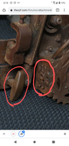
Thanks, the T handle thing I made as I could not find one the right size, it's got a threaded end and screws into place. The other piece again I made, I believe it's from the end bell of an electric motor but as before I couldn't pin it down to a real world item. Here's a close up of the real one, maybe you'll have more luck.We're these circled pieces found parts or custom made? I've about got all the parts together,but these pieces are stumping me! Thanks again for sharing so much info! You're too cool and amazing job again on this,it's spot on!
.jpg")
Petronepaytonsc
New Member
Thanks so much! can't wait to finally get on building mine. Still trying to find someone to ship me an MBO TRS1300p (thats the correct model right?) calculator from the foreign ebays lol such a pain, but i should be able to start after i receive that.Thanks, the T handle thing I made as I could not find one the right size, it's got a threaded end and screws into place. The other piece again I made, I believe it's from the end bell of an electric motor but as before I couldn't pin it down to a real world item. Here's a close up of the real one, maybe you'll have more luck.
View attachment 1463683
KMG79
Active Member
Thank you for the reply. These images would definitely help. Not sure my skill set will allow me to do this, but might try. The main metal parts, is that all thick aluminum? How did you connect everything? Dumb question, but can that be welded?Thanks, I don't have a parts list per se, but I have this image that I did to name some of the parts, hope it helps. Some parts I made, the calculator parts were the hardest to find, I've added pics of the type needed. Hope it helps.
View attachment 1463676View attachment 1463677View attachment 1463678
SATELLITE74
Well-Known Member
I think you could use other models, the 1000 or the 1400. I actually used an Olympia CA120 but had to fabricate one piece to make it more accurate, other Olympia models may work like on the MBO ones, a look inside would be helpful before buying though.Thanks so much! can't wait to finally get on building mine. Still trying to find someone to ship me an MBO TRS1300p (thats the correct model right?) calculator from the foreign ebays lol such a pain, but i should be able to start after i receive that.
SATELLITE74
Well-Known Member
Mine is all aluminium, this can be welded yes, but that's a skill I don't possess, so I pinned and screwed mine together and used JB Weld to simulate the welded areas.Thank you for the reply. These images would definitely help. Not sure my skill set will allow me to do this, but might try. The main metal parts, is that all thick aluminum? How did you connect everything? Dumb question, but can that be welded?
ScoopDiehl
New Member
Your piece is beautiful. I set out this week to put together an approximation of the reverse bear trap only using things I could find in my basement, some ends of foam flooring, miscellaneous junk, wires, cables
 and a buttload of hot glue and super glue. It isn't the beauty you put together, but it'll get me through Halloween!


SATELLITE74
Well-Known Member
well you can certainly see what it's supposed to be, nice job considering the speed build and it looks to be alot easier to wear than mine!Your piece is beautiful. I set out this week to put together an approximation of the reverse bear trap only using things I could find in my basement, some ends of foam flooring, miscellaneous junk, wires, cablesView attachment 1507689 and a buttload of hot glue and super glue. It isn't the beauty you put together, but it'll get me through Halloween!
View attachment 1507693View attachment 1507695View attachment 1507696View attachment 1507697
ScoopDiehl
New Member
Don't plan on wearing one of these metal ones to a Halloween party for hours on-end! The foam one I made is a highly paired-down version which weighs about 3 pounds... My neck was killing me at the end of the night. If you're determined to wear one of the metal ones for the night, start exercising your neck now for next year's party - you'll need it! ")
Last edited:
nayeyinduan
New Member
朋友,不得不说你的动手能力真的很厉害,最近我也在制作这东西,看了你的帖子之后给了我不少启发和灵感。我想知道你制作的可以正常工作吗?就像电影里那样,你是怎样控制他的开合的?
SATELLITE74
Well-Known Member
Hi, thanks. I could not figure a way to get mine to actually work like in the film, though the jaws do open and close manually.朋友,不得不说你的动手能力真的很厉害,最近我也在制作这东西,看了你的帖子之后给了我不少启发和灵感。我想知道你制作的可以正常工作吗?就像电影里那样,你是怎样控制他的开合的?
Maybe you can when you build yours...
BillieThePuppet
New Member
Firstly I wanted to say your replica is amazing.Hi, thanks. I could not figure a way to get mine to actually work like in the film, though the jaws do open and close manually.
Maybe you can when you build yours...
As for functional that's a grey area as one would want safety to be of top concern. That being said if yours opens manually it wouldn't be too hard to convert to how it works in the film. The behind the scenes stuff basically tells you how it works. I know of a build that has the concept down in which I'm buying one after he makes his personal one. He will be doing the venus fly trap as well. This thread has given us some info too. Currently just trying to track down some calculator guts.
SATELLITE74
Well-Known Member
Thanks very much, I'm still quite pleased with how it turned out.Firstly I wanted to say your replica is amazing.
As for functional that's a grey area as one would want safety to be of top concern. That being said if yours opens manually it wouldn't be too hard to convert to how it works in the film. The behind the scenes stuff basically tells you how it works. I know of a build that has the concept down in which I'm buying one after he makes his personal one. He will be doing the venus fly trap as well. This thread has given us some info too. Currently just trying to track down some calculator guts.
Although the jaws are moveable they are quite heavy even made from aluminium so some force would be needed. In the film the actuation appears to be triggered by the stopwatch and the calculator parts as they are seen moving at one point, there is an air ram on one side, but this isn't connected to anything that I can see. It just became too much of a headache for me to figure out how to do it!
I am now working on the Hoffman Bear Trap and this is much easier to get to work because the pnuematic rams on each side are connected to air lines when it opens in the window bars, but it's such a quick cut that you don't really see them.
The calculators of the type required come up on ebay every now and then, but it really helps to see the insides first to confirm the correct inner workings. Good luck.
BillieThePuppet
New Member
The original prop is pneumatic .
I don't believe the timer has any function ( stop watch ) it actually counts up in the film. Its just there for cinematics.
Its also really hard to source .
WwII japanese bomber watch black with 60 seconds - 30 mins
5 sec / 3 min interval dials.
The hose going over the headstrap is an airhose that got connectted to nitrogen. It connected to the Ram you mentioned .
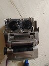
As for Calculator parts I never noticed them moving but find it unlikely as it was gutted from electronics and I doubt they added power to the trap.
Here is what I have but it is one piece so likely will not work.
I'm working on a Billie Replica , the RBT and VFT I am in talks with another builder . Funding RBT at the moment and waiting for parts on VFT too.
The Hoffman RBT ie 2.0 I have a 3d file for that i'll use
Just need to figure out Davids RBT 0.1 lol.
I don't believe the timer has any function ( stop watch ) it actually counts up in the film. Its just there for cinematics.
Its also really hard to source .
WwII japanese bomber watch black with 60 seconds - 30 mins
5 sec / 3 min interval dials.
The hose going over the headstrap is an airhose that got connectted to nitrogen. It connected to the Ram you mentioned .
As for Calculator parts I never noticed them moving but find it unlikely as it was gutted from electronics and I doubt they added power to the trap.
Here is what I have but it is one piece so likely will not work.
I'm working on a Billie Replica , the RBT and VFT I am in talks with another builder . Funding RBT at the moment and waiting for parts on VFT too.
The Hoffman RBT ie 2.0 I have a 3d file for that i'll use
Just need to figure out Davids RBT 0.1 lol.
Attachments
SATELLITE74
Well-Known Member
I fudged my stopwatch together as I couldn't find the correct one. I was sure that I'd seen the calculator parts moving at some point, but I might have been hallucinating due to watching too much footage! The piece you have looks correct, just a bit of cutting to do now...The original prop is pneumatic .
I don't believe the timer has any function ( stop watch ) it actually counts up in the film. Its just there for cinematics.
Its also really hard to source .
WwII japanese bomber watch black with 60 seconds - 30 mins
5 sec / 3 min interval dials.
The hose going over the headstrap is an airhose that got connectted to nitrogen. It connected to the Ram you mentioned .
As for Calculator parts I never noticed them moving but find it unlikely as it was gutted from electronics and I doubt they added power to the trap.
Here is what I have but it is one piece so likely will not work.
I'm working on a Billie Replica , the RBT and VFT I am in talks with another builder . Funding RBT at the moment and waiting for parts on VFT too.
The Hoffman RBT ie 2.0 I have a 3d file for that i'll use
Just need to figure out Davids RBT 0.1 lol.
The pnuematic ram would make the most sense to actually open the jaws, but needs connecting to a reservoir of some sort.
BillieThePuppet
New Member
It's funny you mention the timer being fudged together .
Tyler Haslett's resin model that circled around for a bit used a timer decal I made in 2005 or so in microsoft word.
I have found a black dial with correct clock dial intervals but it has swiss written on the bottom and the company name in the center. That I'm going to have to try to erase. I also hope it will fit in the stop watch I ordered too. Both will take about a month to arrive to me.
I have the exact timer used for VFT in transit too.
I've been watching Amanda's scene over and over for some time now.
The calculator parts looked liked the rip cord got pulled from it. The timer obviously moved but again forwards as it isn't really a timer .
That actually gave me the theory Amanda had 30 mins which is more realistic than 1 for her to do her task. It would take a full revolution of 30 mins to have the dials hit 0, 0
Lets talks how sadistic John was to put timers in locations the players can not see.
My builder has sent me a video in action ( jaws not done ) but it works. The great news is its safe so far as little tension with finger will exhaust the psi. So it would never actually rip a jaw.
I look forward to seeing your RBT 2.0 ( Hoffman )
We are also stuck on the part you believe is a bell housing of some sort. The blueprints say it is a pneumatic chamber but I have yet to find it.
Is the rear ever really shown as I see you have it hollow like .
I think we have the T - Shank handle actually sourced . Problem is my builder and I are in different countries.
You are actually talking to my builder right now too on FB.
Last edited:
SATELLITE74
Well-Known Member
Yes, I'm pretty much talking to you both at the same time! He showed me that video of it working, looks good. My stopwatch is just an online image that I found and I erased some writing on the face and printed it out, I made the hand.It's funny you mention the timer being fudged together .
Tyler Haslett's resin model that circled around for a bit used a timer decal I made in 2005 or so in microsoft word.
I have found a black dial with correct clock dial intervals but it has swiss written on the bottom and the company name in the center. That I'm going to have to try to erase. I also hope it will fit in the stop watch I ordered too. Both will take about a month to arrive to me.
I have the exact timer used for VFT in transit too.
I've been watching Amanda's scene over and over for some time now.
The calculator parts looked liked the rip cord got pulled from it. The timer obviously moved but again forwards as it isn't really a timer .
That actually gave me the theory Amanda had 30 mins which is more realistic than 1 for her to do her task. It would take a full revolution of 30 mins to have the dials hit 0, 0
Lets talks how sadistic John was to put timers in locations the players can not see.
My builder has sent me a video in action ( jaws not done ) but it works. The great news is its safe so far as little tension with finger will exhaust the psi. So it would never actually rip a jaw.
I look forward to seeing your RBT 2.0 ( Hoffman )
We are also stuck on the part you believe is a bell housing of some sort. The blueprints say it is a pneumatic chamber but I have yet to find it.
Is the rear ever really shown as I see you have it hollow like .
I think we have the T - Shank handle actually sourced . Problem is my builder and I are in different countries.
You are actually talking to my builder right now too on FB.
The bell housing is literally that front detail, the chamber part is just an open ended box (see attached picture)
And here's an early stage shot of my 2.0
Well it turns out that I've forgotten how to add images, doh! If someone can advise, please do.(sorted now)
Similar threads
- Replies
- 1
- Views
- 976
- Replies
- 0
- Views
- 1,454
- Replies
- 36
- Views
- 2,196